Calamp
Device Setup
Diagnostics
If your CalAmp device is equipped with status LEDs then please check their status. Both the green GPS and orange Communications LEDs should be solid. If the green LED is off or blinking then no valid GPS position could currently be determined and therefore no positions will be updated on the portal. If the orange LED is off or blinking then no data connectivity has been acquired and therefore no communications will occur with the portal whatsoever.
- In the case of the orange Communications LED not being solid, the first step should be to confirm that the cellular data settings are correct for the SIM card being used.
- In the case of the green GPS LED not being solid, it often takes several minutes for the initial GPS position to be acquired and a GPS time sync to occur.
Setup
The Calamp devices are managed remotely via a central repository, but the devices must be programmed with the APN information before they can connect to the repository. To program a terminal that is new, or changing network operators, do the following:
- Connect the Calamp via a serial port at 115200 bps, 8N1
- Connect via terminal software such as Hyperterm, putty, or screen
- Enter the following commands:
- AT$APP DEBUG ON
- AT$APP PARAM 768,0,137.83.51.39
- AT$APP PARAM 769,0,4763
- AT$APP GPRS CONTEXT 0 “{APN}”
- AT$APP PARAM 2314,0,”{APN Username}”
- AT$APP PARAM 2315,0,”{APN Password}”
- AT$APP GPRS CONTEXT 1 “{APN}”
- AT$APP PARAM 2314,1,”{APN Username}”
- AT$APP PARAM 2315,1,”{APN Password}”
- AT$APP PARAM 1024,35,255,1
- AT$APP PEG ACTION 70 0
- The unit will now reboot. Once the terminal is restarted, enter the following command to force an immediate connection:
- AT$APP PEG ACTION 49 129
- The unit will now download the script from the central repository and begin reporting. This can take up to 30 minutes in poor network coverage.
SMS Setup
The APN information can also be configured via SMS if a serial connection is not an option or it needs to be changed remotely:
- APN:
- !RP,2306,0,{APN}
- APN Username:
- !RP,2314,0,{APN Username}
- APN Password:
- !RP,2315,0,{APN Password}
- Server IP Address for:
- (32 bit LMU) !RP,768,0,137.83.51.39
- (8 bit LMU) !RP,2319,0,137.83.51.39
- (8 bit LMU) !RP,2319,1,137.83.51.39
- Server UDP Port:
- !RP,769,0,4763
- Reset Device:
- !R3,70,0
- Send Maintenance Report (to download configuration updates):
- !R3,49,129
Upgrading Firmware
Use a serial terminal program such as HyperTerm with the YModem protocol
- If you do not have HyperTerminal you can use a free utility here: http://en.sourceforge.jp/projects/ttssh2/releases/
- Open the terminal program (HyperTerm) and connect to the serial port at 115200 8N1
- Enter “ATDNLD” and the unit will be ready for the file transfer
- Using the YModem protocol, send the firmware binary to the unit
Firmware: LMU-GSM-170-30g.bin LMU-26xx and LMU-27xx GSM ONLY
Firmware: LMU-HSPA-176-33b.bin LMU-4x5x Iridium and GSM
Updating Configuration Locally
Download this [{UP(Calamp)}AppendCRC16ToBin.exe|AppendCRC16toBin.exe] program to convert scripts to directly loadable files
- If you do not have HyperTerminal you can use a free utility here: http://en.sourceforge.jp/projects/ttssh2/releases/
- Start here to export your script from LMU Manager. If you already have a script ready, skip to “Loading the script” below.
- Export the script from LMU manager to a CSV
- Open Command prompt and enter ‘AppendCRC16toBin.exe’ and then the name of the script file you want to convert
- Once this has finished it will have overwritten the existing script file and added characters at the end of the parameter list.
- Loading the script
- Using HyperTerm
- Open the terminal program (HyperTerm) and connect to the serial port at 115200 8N1
- Enter “ATDSCFG” and the unit will be ready for the file transfer
- Using the YModem protocol, send the configuration file (.csv) to the unit
- Press ‘Send’ button. You should see a list of the records being written.
- Using Tera Term
- Open the terminal program (Tera Term) and connect to the serial port at 115200 8N1
- Enter “ATDSCFG” and the unit will be ready for the file transfer
- Go to File -> Transfer -> YMODEM -> Send and select the configuration file (.csv) to send to the unit
- Press ‘OK’. You should see a list of the records being written.
- Using HyperTerm
RSSI
Signal Strength Equivalents
| Signal Level | Bars | RSSI Range |
|---|---|---|
| Great | 5 | >= -77 |
| Good | 4 | >= -78 < -86 |
| Average | 3 | >= -87 < -92 |
| Poor | 2 | >= -93 < -101 |
| Bad | 1 | < -102 |
LMU-26x0/LMU-27x0
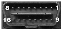
Pinout
PDF: 5C908 Datasheet
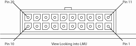
| Pin | Signal Name | Description | 5C908 Color | Input or Output |
|---|---|---|---|---|
| 1 | GND | Ground | Black | Ground |
| 2 | OUT-1 | Output 1 – Starter Disable Relay Driver | Green | Output |
| 3 | IN-1 | Input 1 – Digital Input | Blue | Input |
| 4 | SER_IN | Serial Input | Blue | Input |
| 5 | ADC-1 | Analog to Digital Input 1 | Pink | Input |
| 6 | IN-3 | Input 3 – Digital Input | Violet | Input |
| 7 | IN-4 | Input 4 – Digital Input | Grey | Input |
| 8 | IN-0 | Ignition | White | Input |
| 9 | VDD | VDD Reference Output (20-25mA Max) | Orange | Output |
| 10 | OUT-2/BOOT | Output 2 – Digital Output (Open Collector) BOOT Input | Brown | Input / Output |
| 11 | OUT-3 | Output – 3 Digital Output (Open Collector) | Yellow | Output |
| 12 | IN-2 | Input 2 – Digital Input | Orange | Input |
| 13 | SER_OUT | Serial Output | Green | Output |
| 14 | VCC | Primary Power Input | Red | Power |
| 15 | GND | Primary Ground | Black | Ground |
| 16 | 1BB-GND | 1 Bit Bus Ground | Black | Ground |
| 17 | 1BB-D | 1-Bit Bus Data | White/Blue | Input / Output |
| 18 | Aux - TxD | Aux Port 2 - Transmit Data | White/Orange | Input |
| 19 | Aux - GND | Aux Port 2 - Ground | Black | Ground |
| 20 | Aux - RxD | Aux Port 2 - Receive Data | White/Yellow | Output |
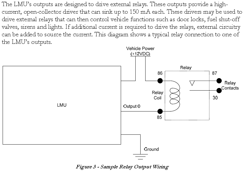
Relay Wiring
LMU-3000
Configuration
- Connect pin 16 to battery +
- Connect pin 4 to ground
- Connect serial port interface
- Follow “Setup” instructions above to program the APN
Pinout
| Pin | Signal Name | Description |
|---|---|---|
| 2 | Bus+ Line | SAE-J1850 PWM and SAE-1850 VPW |
| 4 | Chassis Ground | Ground |
| 5 | Signal Ground | Ground |
| 6 | Can High | ISO 15765-4 and SAE-J2284 |
| 7 | K line | ISO 9141-2 and ISO 14230-4 |
| 10 | Bus- Line | SAE-J1850 PWM and SAE-1850 VPW |
| 14 | Can Low | ISO 15765-4 and SAE-J2284 |
| 15 | L line | ISO 9141-2 and ISO 14230-4 |
| 16 | Battery Power | Power |
LMU-4250
Pinout
| Pin | Signal Name | Description | Color | Input or Output |
|---|---|---|---|---|
| 1 | VIN | Primary Power | Red | Power |
| 2 | GND | Ground | Black | Ground |
| 3 | INPUT 0 | Input 0 - Ignition | White | Input |
| 4 | ADC1 | Analog to Digital Input 1 | Pink | Input |
| 5 | VIN_FILT | Brown/Red | ||
| 6 | AUX1_VCC | Aux Port 1 - Power | Brown/Orange | Power |
| 7 | GND | Ground | Black | Ground |
| 8 | AUX1_RX | Aux Port 1 - Receive Data | Brown/Green | Input |
| 9 | AUX1_TX | Aux Port 1 - Transmit Data | Brown/Blue | Receive |
| 10 | VIN_FILT | Yellow/Red | ||
| 11 | AUX2_VCC | Aux Port 2 - Power | Yellow/Orange | Power |
| 12 | AUX2_RX | Aux Port 2 - Receive Data | Yellow/Green | Input |
| 13 | AUX2_TX | Aux Port 2 - Transmit Data | Yellow/Blue | Output |
| 14 | INPUT 1 | Input 1 - Digital Input | Blue | Input |
| 15 | INPUT 2 | Input 2 - Digital Input | Orange | Input |
| 16 | INPUT 3 | Input 3 - Digital Input | Violet | Input |
| 17 | INPUT 4 | Input 4 - Digital Input | Gray | Input |
| 18 | INPUT 5 | Input 5 - Digital Input | Green/White | Input |
| 19 | INPUT 6 | Input 6 - Digital Input | Blue/White | Input |
| 20 | INPUT 7 | Input 7 - Digital Input | Black/White | Input |
| 21 | 1BB_T_DATA | 1-Bit Bus Transmit Data | Green/Black | Output |
| 22 | 1BB_GND | 1-Bit Bus Ground | Black | Ground |
| 23 | 1BB_R_DATA | 1-Bit Bus Receive Data | Orange/Black | Input |
| 24 | OUTPUT 0 | Output 0 - Digital Output | Green | Output |
| 25 | OUTPUT 1 | Output 1 - Digital Output | Brown | Output |
| 26 | OUTPUT 2 | Output 2 - Digital Output | Yellow | Output |
| 27 | OUTPUT 3 | Output 3 - Digital Output | Blue/Orange | Output |
| 28 | OUTPUT 4 | Output 4 - Digital Output | White/Yellow | Output |
| 29 | LED OUTPUT 1 | Output 5 - LED Driver | Red/Green | Output |
| 30 | LED OUTPUT 2 | Output 6 - LED Driver | Orange/Green | Output |
| 31 | ADC2 INPUT | Analog to Digital Input 2 | Black/Red | Input |
| 32 | ADC3 INPUT | Analog to Digital Input 3 | White/Red | Input |
| 33 | ADC4 INPUT | Analog to Digital Input 4 | Orange/Red | Input |
| 34 | ADC5 INPUT | Analog to Digital Input 5 | Blue/Red | Input |
I/O Descriptions
- Digital Inputs
- Input 0: Ignition Sense (Always biased low)
- Input 1: Generic Digital Input (Biased high or low/ S-158 Bit 1)
- Input 2: Generic Digital Input (Biased high or low/ S-158 Bit 2)
- Input 3: Generic Digital Input (Biased high or low/ S-158 Bit 3)
- Input 4: Generic Digital Input (Biased high or low/ S-158 Bit 4)
- Input 5: Generic Digital Input (Biased high or low/ S-158 Bit 5)
- Input 6: Generic Digital Input (Biased high or low/ S-158 Bit 6)
- Input 7: Generic Digital Input (Biased high or low/ S-158 Bit 7)
- Input 8: Motion Sensor
- Input 9: VBUS Active
- Input 10: Power State
- Input 11: Vbatt Low
- Analog to Digital Inputs
- A/D 0: External Power Supply Monitor
- A/D 1: Generic External Analog to Digital Input
- A/D 2: Generic External Analog to Digital Input
- A/D 3: Generic External Analog to Digital Input
- A/D 4: Generic External Analog to Digital Input
- A/D 5: Generic External Analog to Digital Input
- A/D 6: GPS Antenna Monitor
- A/D 7: GPS Antenna Monitor
- A/D 8: Internal Temp Monitor
- A/D 9: Vref
- A/D 10: Battery Voltage
- Outputs:
- Output 0: Standard Open Collector Relay Output
- Output 1: Standard Open Collector Relay Output
- Output 2: Standard Open Collector Relay Output
- Output 3: Standard Open Collector Relay Output
- Output 4: Standard Open Collector Relay Output
- Output 5: Standard LED Driver
- Output 6: Standard LED Driver
- Output 7: Power Switch
- Output 8: Charge Disable
- iButton / 1 Bit Bus
- iButton ID Support
- 1-Wire bus with current boost for temperature sensors
Sensors and Accumulators
The platform is by default setup to accept temperature in accumulator 0 and fuel level in accumulator 1.
The temperature is received in Celsius and is multiplied by 16.
The fuel level which is translated to a voltage is multiplied by 1000. IE 4800 translates to 4.8V
Fuel
The Calamp series can be connected to a VDO device which translates the fuel level with a tank profile into a sliding scale voltage of 0 to 10 volts which represents a fuel level of empty to entirely full.
The Ultrasonic-Fuel-Sensor-UL-200 is also supported.
1-Wire Sensors
The Calamp series supports 1-Wire temperature sensors. Temperature sensors based on the DS18B20 support a single sensor, and the DS28EA00 supports up to 8 sensors in a chain.
https://www.sparkfun.com/products/11050
Single temperature sensor model 1WT_6SSP_1_5m_2w
- Red: Connect to Calamp GND - Black wire
- White: Connect to Calamp 1 Wire Data - White/Blue Stripe
- Datanab
Up to 8 temperature sensors daisy-chained: Datanab
Temperature plus Humidity sensor (HTS Sensor)
https://www.adafruit.com/product/393
- Sample configuration for LMU27xx 27xx-sample-calamp-humidity.csv
- Firmware version MUST be 3.7b or higher
- Bit 0 of S register 171 must be cleared (IE: 0)
-
Bit 4 of S register 181 must be set (IE: 16)
- Wire HTS Sensor Red to 5V (Pin 9: Orange)
- Wire HTS Sensor White/Black to GND or 1BB GND (Pin 1 or 16: Black)
- Wire HTS Sensor Yellow to 1BB Data (Pin 17: White/Blue)
LMU-2xx0
To connect a single temperature sensor, connect the DATA pin of the temperature sensor which is typically white on a 4 wire model and red on a 2 wire model to the White/Blue wire on the Calamp. Then connect the GND wire which is typically black to any ground/black wire of the Calamp.
Notes
- To enable the 1-wire bus the S register 171 must be set to 65. Ex: “ATS171=65”
- To push the temperature sensor data to the accumulator, the PEG Action Move Temp Sensors to Accumulator (93) can be used. Ex: “AT$APP PEG ACTION 93 0” sets temperature sensor 0 to push its value to accumulator 0
- To transmit the accumulator over the air, the Accumulator Number (772, 773) must be set to the number of accumulators to transmit under Report Contents > Event Report Optional Contents > Accumulator Number in LMU Manager: Ex: 1
Position Size
Standard position reports are 54 bytes + UDP header (minimum of 28 bytes) = 82 bytes minimum depending on TCP header size